Coil Manufacturing
Ridgway Machines manufactures a full range of Coil Manufacturing Equipment, including Rotor Winders, Loop Winders and ancillary equipment such as Capstan Tension Units, Winding Beams Coil Pull-Out Machines and Drum Stands. Manufactured to high specifications and incorporate the latest safety features and fully programmable operator control.
LWDS - Loop Winder Drum
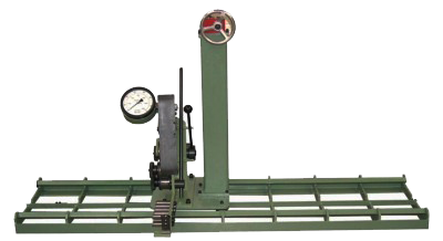
The LWDS Loop Winder Drum Stand range is designed to compliment Ridgway’s range of loop winders during the loop winding process. A fabricated steel frame with cantilever drum shafts support the conductor drums. The number of drum positions can be configured to suit individual customer requirements.
![]() The drum shafts carry individual back tension brakes, comprising of a brake drum onto which a brake shoe operates.
The drum shafts carry individual back tension brakes, comprising of a brake drum onto which a brake shoe operates.
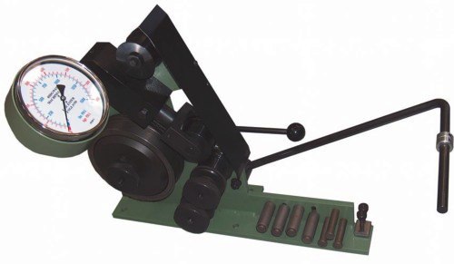
![]() Each drum shaft has individual tension adjustment. The tension adjustment is provided via a pneumatic cylinder connected to an individual lever valve with a pressure regulator and visual pressure gauge.
Each drum shaft has individual tension adjustment. The tension adjustment is provided via a pneumatic cylinder connected to an individual lever valve with a pressure regulator and visual pressure gauge.
Technical Specification
MODELS
LWDS2 | LWDS4 | LWDS6 | LWDS8 | LWDS10 | LWDS12 |
Max Drum Diameter
800mm
Max Drum Width
300mm
Weight Of Drum
150kg
Drum Configuration
LWDS2 – 2×1 | LWDS4 – 2×2 | LWDS6 2×3 | LWDS8 2×4 | LWDS10 2×5 | LWDS12 2×6|
Active drum tension control
Compared to the alternative of the LWDS friction braking, active tensioning offers a wear free solution with accurately controllable individual constant drum tensions.
Tension adjustment for each drum is provided via a HMI on the winder control panel. Tension range is 0 – 35kg per drum and is constant throughout the life of the drum.


LWDS-R – Loop Winder Drum Stand
The LWDS-R Rotating Loop Winder Drum Stand range is designed to rotate 180 degrees to assist in end-winding transposition of looped coils during the loop winding process. The number of drum positions can be configured to suit individual customer requirements.
The drum shafts also carry the back tension brake, comprising of a brake drum onto which a brake shoe operates. Tension adjustment for each drum is provided via a cylinder connected to a lever valve and a pressure regulator. Each brake system can be switched on or off via the hand operated valve, with the tensions adjusted by the pressure regulator next to each hand valve, with a pressure gauge for reference.
The fabricated frame is fixed to a front and rear support structure. Each of these structures includes a bearing system – the rear system consists of a slewing ring arrangement to enable the drum frame to rotate 180 degrees. Rotation of the slewing ring is controlled via a motor and drive system that is operated from a control panel located adjacent to the drum stand. The system is designed to rotate 180 degrees in one direction then back again.
Technical Specification
Max Drum Diameter
800mm
Max Drum Width
300mm
Max Drum Weight
150 kg
Drum Shaft Diameter
Ø 32mm
![]() Cantilevered drum shafts, each with twin bearing units. The drums are mounted to the drum shafts by means of tapered cones to accept a range of drum bore sizes.
Cantilevered drum shafts, each with twin bearing units. The drums are mounted to the drum shafts by means of tapered cones to accept a range of drum bore sizes.
![]() The drum shafts also carry the back tension brake, comprising of a brake drum onto which a brake shoe operates. Tension adjustment for each drum is provided via a cylinder connected to a lever valve and a pressure regulator.
The drum shafts also carry the back tension brake, comprising of a brake drum onto which a brake shoe operates. Tension adjustment for each drum is provided via a cylinder connected to a lever valve and a pressure regulator.
![]() Each brake system can be switched on or off via the hand operated valve, with the tensions adjusted by the pressure regulator next to each hand valve, with a pressure gauge for reference.
Each brake system can be switched on or off via the hand operated valve, with the tensions adjusted by the pressure regulator next to each hand valve, with a pressure gauge for reference.

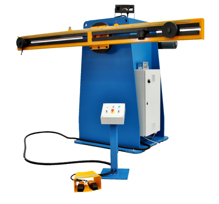
W-LMP - Loop Winder
For a versatile and cost effective solution to suit your loop winding requirements.
Sturdy construction, free standing control panel and digital turns counter are key features of our loop winding solutions.
Technical Specification
Model Loop Winding Beam
LWWB 1500 | 2000 | 3000 | 5000
Length of Loop
LWWB min 350mm –
1500mm | 2000mm | 3000mm | 5000mm
Pin Diameter
min 12mm – max To suit cutomer requirements
Conductor Width
min 3mm – max 50mm
Lead Clamp
YES
D-Loop Tooling
Optional
![]() Vector motor drive
Vector motor drive
The W-LMP incorporates the latest vector drive technology. A variable speed geared motor directly drives the main spindle, providing a high torque capability with soft start.
![]() Quick release tooling
Quick release tooling
Operator friendly solutions for both the
conductor clamping and winding pin assemblies. Optional “D” loop tooling also available.
![]() Operator controls
Operator controls
Easy to operate control panel for the adjustment of winding speed and direction of rotation. Large digital turns counter with reset capability.
![]() Guides
Guides
Free standing, adjustable conductor guides are incorporated into the winding line as standard.
![]() Quick, accurate set up
Quick, accurate set up
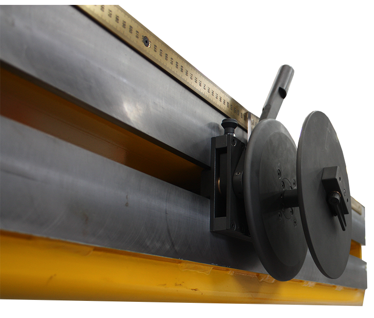
All winding beams incorporate a pair of fully adjustable winding pins and a conductor
clamping arrangement. For reference, scales are fitted to the winding beam, ensuring fast and accurate set-ups can be achieved.
![]() Anti-run back
Anti-run back
The winder incorporates an electrically released brake, preventing run back and
eliminating tension loss during stopping and starting.
![]() Operator platforms
Operator platforms
Optional work platforms are available, designed to ensure a safe working environment for your operators.
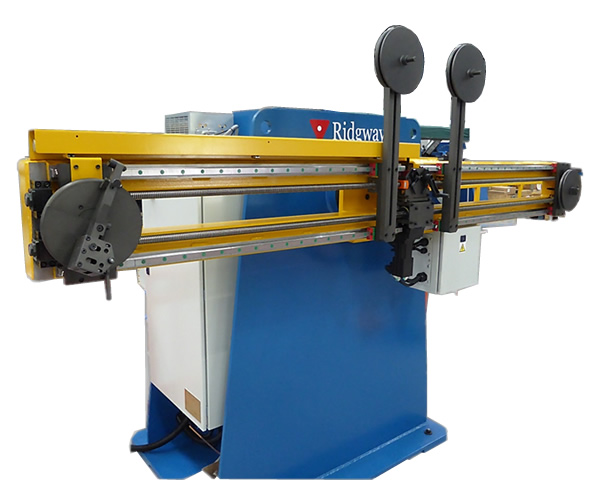
W-LAP - Loop Winder
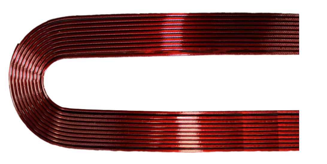
The range of Ridgway’s W-LAP Loop Winders are used to manufacture precise multi turn looped coils.
Automatic programmable pin positioning, combined with conductor gathering and guidance systems ensure precise and consistent quality.
Technical Specification
Model
W-LAP 1500 | 2000 | 3000 | 5000 | 7000
Maximum Torque
W-LAP 1500Nm | 2000Nm | 3000Nm | 5000Nm | 7000Nm
Speed Range
W-LAP 1500 – 0 to 25 rpm
W-LAP 2000 | 3000 | 5000 – 0-20 rpm
W-LAP 7000 – 0-15 rpm
![]() Programmable Winding
Programmable Winding
Automatic winding pin positioning and end of cycle release.
![]() Tooling
Tooling
Optional D-Loop tooling available
![]() Improved quality
Improved quality
Fast, accurate and consistent winding of looped coils.
![]() Anti-run back
Anti-run back
The winder incorporates an electrically released brake, preventing run back and eliminating tension loss during stopping and starting.
![]() Quick release tooling
Quick release tooling
All winding beams incorporate a pair of fully adjustable winding pins and a conductor
clamping arrangement. For reference, scales are fitted to the winding beam, ensuring fast and accurate set-ups can be achieved
![]() Conductor gathering and guidance
Conductor gathering and guidance
Conductor gathering and guidance systems ensure precise and consistent quality.
![]() Servo motor drives
Servo motor drives
The W-LAP incorporates the latest servo drive technology.
![]() Operator HMI control
Operator HMI control
Easy to operate control panel for the adjustment of loop length, winding speed. Other functions include the ability to set and count the number of turns per coil and the quantity of coils per set. Coil winding details can also be stored within the control system for future use.
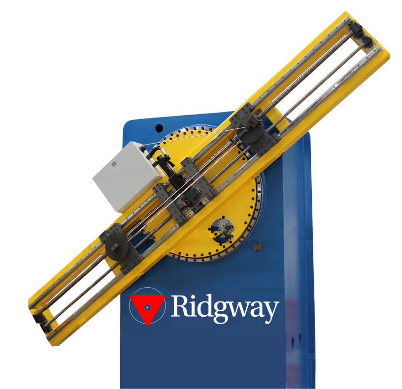
W-3DW - 3D Multi - Axis Winder
Designed for organisations that need complex 3D-shaped coils for various applications.
The Ridgway Multi-Axis Coil Winding Machine meets these needs by winding coils in
multiple planes.
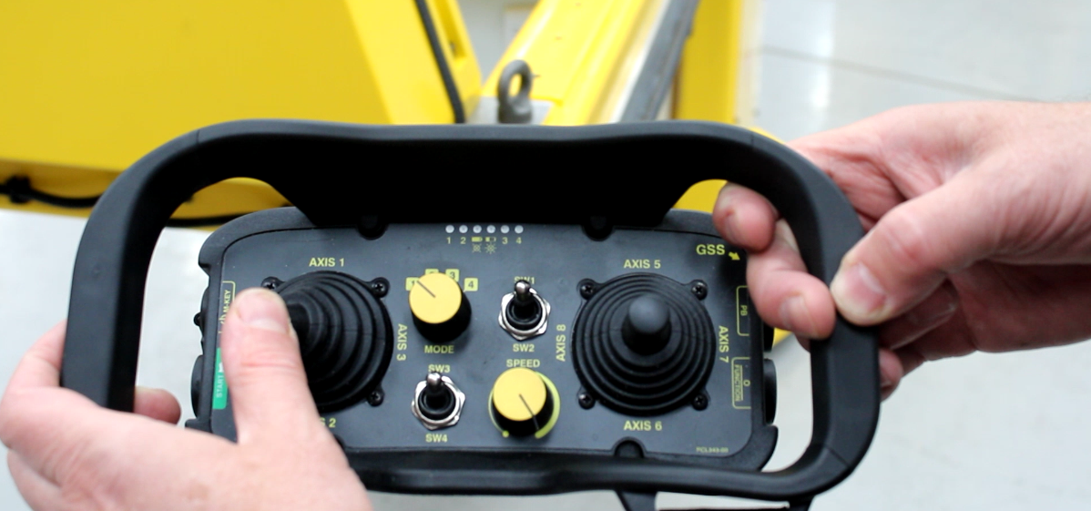
The operator control unit features a wireless controller linked to the machinery control system, allowing the operator to safely approach the coil winding area.
Technical Specification - Pay-Off Drum Stand
Max Drum Diameter
600mm
Max Drum Width (Height)
350mm
Max Drum Weight
75kg
Max Pay-Off Speed
10rpm
Conductor Tension
50N to 500N +/-10%

Technical Specification - Coil Winding Machine
Max Beam Rotation Speed
4rpm
Max Beam Torque
750Nm
Max Beam Spindle Rotation Speed
4rpm
Max Beam Spindle Torque
650Nm
Max Conductor Size
30mm H x 10mm W
Max Height Movement (Y AXIS)
750mm
Max Side to Side Movement (X AXIS)
2600mm
Max Conductor Rotation (C AXIS)
+/-120 ° from datum axis
Max Linear Movement Speed
20mm per second
Max Conductor Rotation Speed
30 ° per second
W-MAW - Multi-Axis Winder
Improve production effectiveness by utilizing the Ridgway W-MAW. Incorporating a programmable multi-axis winding machine with active drum tensioning and conductor guidance systems, the equipment ensures fast, consistent and high quality production of complex shaped stator coils.

Technical Specification
Loop Winder
Maximum torque
Up to 9000 Nm
Speed range
0 to 10 rpm
Fully programmable
Winding Beam
Maximum length
Up to 2.5 metres
Servo controlled beam positioning
Servo controlled tool rotation
![]() Main spindle drive
Main spindle drive
The W-MAW incorporates the latest servo drive technology. A variable speed geared motor directly drives the main spindle, providing a high torque capability throughout the speed range.
![]() Multi-axis winding beam
Multi-axis winding beam
Encoder feedback ensures accurate positional control of the winding beam. An additional servo driven gearbox, mounted directly to the winding beam also provides rotational movement of the coil tooling.
![]() Conductor guidance
Conductor guidance
The W-MAW incorporates the latest servo drive technology. A variable speed geared motor directly drives the main spindle, providing a high torque capability throughout the speed range.
![]() Operator control
Operator control
Conductor guidance is provided via a free standing guide post to ensure vertical, horizontal and angular positioning is maintained. Additional servo controlled conductor guidance can also be fitted to the coil tooling if required.
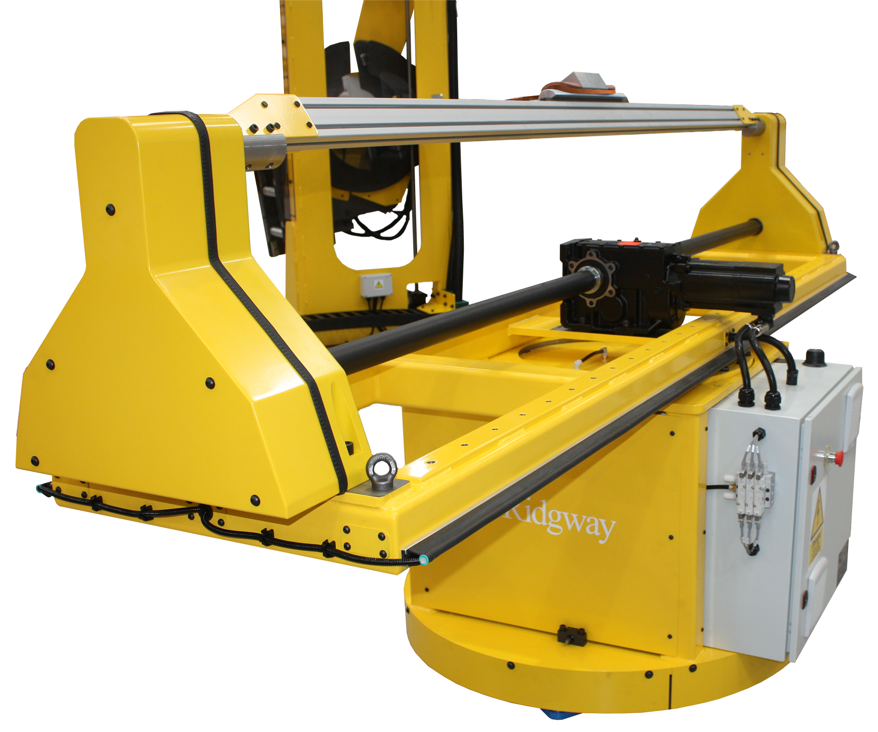
W-RHD - Rotor Winding Machine
For a complete solution to enable the fast and effective winding of rotor pole coils.

Technical Specification
Maximum torque
Up to 10000 Nm
Speed range
0 to 10 rpm
Maximum rotor weight
W-RHD5000 – up to 5000kg
W-RHD10000 – up to 10000kg
Faceplate centre height
1300mm (other heights available)
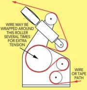
Ridgway Capstan Tension Unit
Variable tension control
Adjustable guide rollers
Pneumatic brake override
![]() Geared servo drive system
Geared servo drive system
The W-RHD incorporates the latest servo drive technology. A variable speed geared motor
directly drives the main spindle, providing a high torque capability throughout the speed range.
![]() Pneumatic holding brake
Pneumatic holding brake
The spindle is fitted with a pneumatic holding brake to ensure a positive stop.
![]() Operator controls
Operator controls
The main control panel used to vary speed and direction of rotation is mounted on a
free-standing pedestal giving greater operator flexibility.
![]() Indexing
Indexing
Conductor guidance is provided via a free standing guide post to ensure vertical, horizontal and angular positioning is maintained. Additional servo controlled conductor guidance can also be fitted to the coil tooling if required.
![]() Tooling and fixtures
Tooling and fixtures
Providing you with greater flexibility, a large faceplate is fitted as standard to enable easy
direct fitting of existing tooling. Exclusive tooling/fixture design can also be incorporated offering you a complete solution.
The W-MAW & W-RHD both incorporate a Capstan Tension Unit

For optimum conductor control a range of pneumatically actuated single or double capstan tension units are available. This capstan tension unit is a fabricated steel frame forming a rigid structure onto which all other components are mounted. Four fixing holes are included to fix the unit to the floor.
A capstan wheel is mounted onto a shaft to which a brake disk is mounted for a
pressure regulated brake calliper unit. Increasing the air pressure increases the brake strength thus increasing the tension of the conductor between the tensioner and the next machine in the line. Fleeting wheels are fitted around the capstan wheel to push the cable across the wheel as it rotates. The wheel is guarded all around with an interlocked access door fitted to the front of the unit.
Available in two sizes
| Max.250kg | 2500N |
| Max.500kg | 50000N |
![]() Variable tension control
Variable tension control
![]() Adjustable guide rollers
Adjustable guide rollers
![]() Pneumatic break override
Pneumatic break override
![]() Electrically driven option
Electrically driven option
![]() Center line height can be customized to suit exact requirements
Center line height can be customized to suit exact requirements
Technical Specification
Model
HCP1000 | 2000 | 3000 | 4000
Tooling Space Availability
Max. 325mm W x 250mm H
Pressing Space Availability
Max. 275mm W x 220mm H
Loop Length
1500mm | 2500mm | 3500mm | 4500mm
Pressing Length
1000mm | 2000mm | 3000mm | 4000mm
Heating Temperature
Typically 165 °C
Number of Press Heads
4 | 8 | 12 | 16
Compaction Force
10 Tonnes per cylinder (Horizontal & Vertical)
Hydraulic System
Powered by Air Multiplier
Heater Platerns
Nominally 500mm L x 220mm H x 50mm W
Heater Platern Power
Nominally 12Kw (per heater platen)
Cooling Circuit
With air blast and recyclable water cooling
The HCP Hot Coil Compaction Press is designed to heat and consolidate stator coils & bars. Standard models are available however, each machine can be tailored to the customer’s specific requirements.
The HCP incorporates a set of hydraulic rams built into hinged arm assemblies across the top length and rear face of the working envelope, with independent hydraulic circuits. Each ram can deliver 10 tonnes of force and the number of rams can be selected to suit specific coil lengths.
Coil heating is achieved using a set of electrically heated platens (heater bars) at the front and rear sides of the machine. Each platen is independently operated/controlled from a
free standing HMI cabinet.
After pressure is applied, the platen temperature is raised to a set point and held for a period of time (soak time). The platens are then cooled with an air blast followed by recyclable cooling water prior to hydraulic ram release and unloading of the coils.
![]() Full HMI Process Control
Full HMI Process Control
Full HMI operator control is provided from a free standing cabinet. This covers the entire compaction process from hydraulic, air and temperature control to cooling and power consumption for each of the control zones within the machine, including fault diagnosis.
![]() Heater Platens
Heater Platens
Available in a range of sizes
![]() Press space availability
Press space availability
Can be configured to suit exact requirements
![]() Water chiller/ Recirculating Unit
Water chiller/ Recirculating Unit
Interfaced with the HCP through a water manifold arrangement and controlled via the PLC.
HCC – Hot Coil Compaction Press
Designed to heat and consolidate straight loop stator coils


POM-STD – Coil Pull-Out Machine
Technical Specification
Coil stack height
Dependent on tooling
Coil stack width
Dependent on tooling
Slot length
Max: 4064mm
Min: 115mm
Overall loop length (eye to eye)
Max: 5300mm
Min: 875mm
Angle between coil sides
Max: 120° (included)
Min: 0°
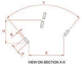
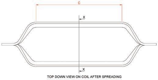
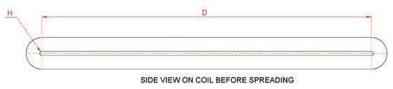
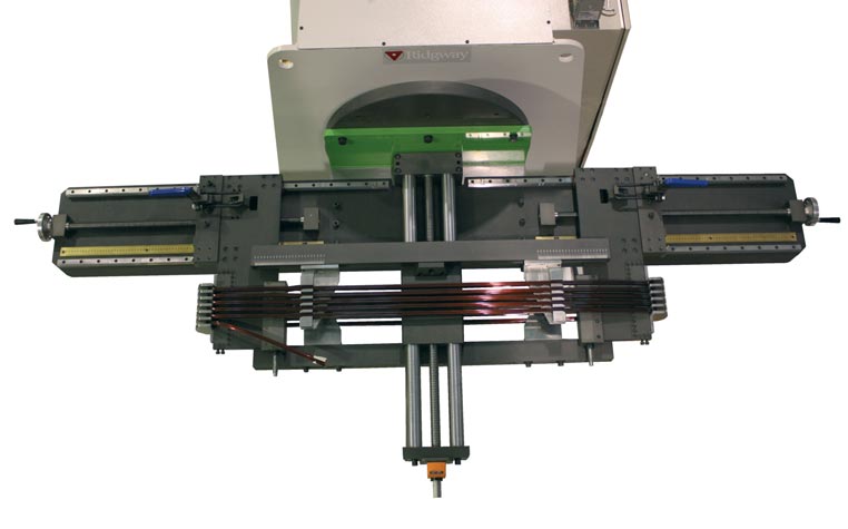
The POM-STD range of coil forming machines are used to spread coils quickly, accurately and efficiently into their final shape according to the coil design.
![]() Capabilities
Capabilities
Pneumatically powered, the POM-STD range has the capability to form stator coils having a maximum loop length of 2500mm with a maximum coil stack size of 60mm x 30mm
![]() Adjustable tooling
Adjustable tooling
Fall away pin type knuckle holders guarantee firm clamping action and quick release. Both the length and the thickness of the coil knuckle holders are adjustable.
![]() Easy to operate
Easy to operate
The coil forming process is driven by using air pressure. Little manual effort is required of the operator. After the loop has been loaded, actuation of a foot pedal closes all four slot clamps simultaneously. The exclusive ballast tank minimizes air supply fluctuations, producing coils smoothly and quickly.
![]() Easy to set
Easy to set
For reference, linear scales are fitted to ensure repeat accurate set ups are quickly and easily achieved.
POM-WPB – Wind & Pull-Out Beam
Technical Specification
Coil stack height
Max: 50mm
Min: 10mm
Coil stack width
Max: 17mm
Min: 5mm
Length of cell (coil straight)
Max: 1520mm
Min: 440mm
Overall loop length (eye to eye)
Max: 2300mm
Min: 756mm
Winder
Maximum torque
Up to 5000 Nm
Speed range
0 to 20 rpm
Bi-directional
For a versatile and cost effective solution the POM-WPB wind and pull-out beam offers a simple production solution to dramatically reduce the overall coil manufacturing time. The POM-WPB enables phase groups of single and multi-turn coils to be loop wound and pulled-out in one operation.
![]() Quick, accurate set up
Quick, accurate set up
The POM-WPB is fully adjustable. For reference, linear scales are fitted to the beam, ensuring fast and accurate setups can be achieved.
![]() Tooling and fixtures
Tooling and fixtures
Exclusive bespoke tooling design is incorporated, offering a complete manufacturing solution. Variable length
slot section and interchangeable loop bend radius tooling are available.
![]() Turn-key solution
Turn-key solution
The wind and pull-out beam is a standalone fixture designed to fit to an existing winding machine faceplate.
Offering a turn-key solution, to complement the POM-WPB, a complete range of winding machines and drum
stands is also available.
![]() Operator platforms
Operator platforms
Optional work platforms are available, designed to ensure a safe working environment for your operators.
POM-CC – Continuous Coil Forming
Technical Specification
Coil stack height
Dependent on tooling
Coil stack width
Dependent on tooling
Length of cell (coil straight)
Max: 1000mm
Min: 380mm
Overall loop length (eye to eye)
Max: 2000mm
Min: 875mm
Angle between coil sides
Max: 120° (included)
Min: 0°
Coil spread
Max: 900mm
Min: 150mm
The POM-CC range of coil forming machines are used to spread coils quickly, accurately and efficiently into their final shape according to the coil design. Enabling the fast and effective winding of stators, this turn-key production solution dramatically reduces the number of winding
connections required. Simple to operate, production efficiencies of 50% can easily be achieved.
![]() Turn-key solution
Turn-key solution
To complement the POM-CC, a complete range of loop winders, loop winder tooling, turn tapers and drum stands is available.
![]() Precision control
Precision control
Resolver feedback ensures accurate and repeatable positioning of the machine axes.
![]() Tooling and fixtures
Tooling and fixtures
Exclusive bespoke tooling design is incorporated offering a complete manufacturing solution.
![]() Operator HMI control
Operator HMI control
Easy to operate control console via HMI to enable operation of the machine and programming of the pull-out sequences. Coil winding details can also be stored within the control system for future use.
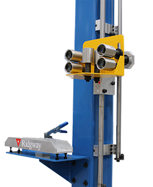
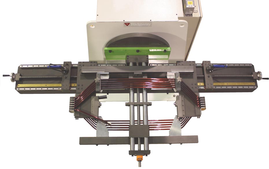
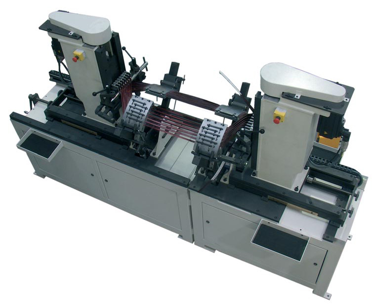
NCT - Narrow Coil Taping Machine
The Ridgway NCT Narrow Coil Taping machine offers an advanced and cost effective automated solution for taping narrow profile wind turbine generator stator coils.
The NCT features a unique multi-axis motion control system with a free standing programmable HMI, making it a truly versatile machine that simplifies the precision taping of all narrow coil configurations, straight or diamond shaped.
The innovative design solves a common problem where traditional taping machines have limited access to both sides of the coil. The coil support system features automatic coil turn-over and height adjustment. This simplifies set-up and eliminates the need to remove or reposition a coil to tape both sides.
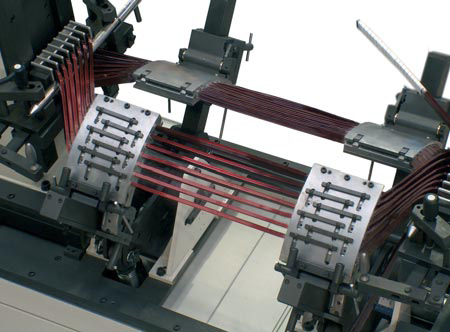
![]() Unique Taping Motion
Unique Taping Motion
The NCT uses a unique multi-axis head motion. Lateral movement of the NCT taping head is controlled via a servo motor driven ball screw. This in turn is synchronised with the servo motors that drive the rotational aspects of the taping head. The action of this complex head motion results in a precise process that consistently provides high
quality taped coils.
![]() Constant Tension Control
Constant Tension Control
The Ridgway NCT features constant tension control between 20N and 50N.
![]() Fully Programmable
Fully Programmable
The machine is fully programmable, for example, to set the number of layers required for each coil side, tape pitch and linear speed, the angle of diamond coil legs. Auto reverse at the end of each pass allows for uninterrupted, multiple tape layers without downtime.

![]() User Friendly HMI Control
User Friendly HMI Control
Operated via a user friendly HMI control module, the Ridgway NCT provides the end user with a simple, reliable coil taping solution. For manufacturers of wind turbine generator stator coils, taping productivity and quality will be increased on all narrow coil requirements.
Technical Specification
Rotational Speed
60 rpm max
Tape Width
20mm/25mm
Pitch Capability
5mm to 28mm
Tape Tension
20N to 50N
Tape Angle
+/- 20 °
Coil Length
min 700mm
max 3000mm
Distance Between Coil Sides
min 65mm
max 500mm
Coil Cross Section Height
min 25mm
max 160mm
Coil Cross Section Width
min 10mm
max 25mm
Max Coil Weight
200kg

![]() Taping Head
Taping Head
The taping head rotates around the coil applying a pair of tapes simultaneously with the tensions between 0.5kg and 7.0kg. Tape reel carriers automatically follow the natural angle of the tape being applied to the coil in relation to the coil axis. The MTM head can apply tapes at a rotational speed of up to 250 rpm.
![]() Drive System
Drive System
The MTM uses twin variable speed motors to provide and synchronise the taping head drive and carriage traverse functions. These are controlled by a foot pedal mounted on the taping head carriage, with reversing selection by joystick control.

![]() Coil Support
Coil Support
Pneumatically assisted coil support and clamping system with 3 retractable arms, fully adjustable rear clamp stands and coil eye clamps/supports.
![]() Safe Guarding
Safe Guarding
The MTM is equipped with fixed mesh screen fencing on 3 sides for operator safety. On the open side of the machine enclosure an electronic light sensor guard automatically detects any intrusion and activates the safety circuit, cutting power to stop the machine.
MTM - Mobile Travelling Head Coil Taping
The MTM Mobile/Travelling Head Coil
Taping Machine provides a unique solution to maximise the productivity of applying insulation tapes to larger size electrical coils or bars, with a typical slot length capacity of up to 4000mm.
Ridgway’s MTM is specifically designed for
handling these larger size coils/bars using a
combination of retractable pneumatic coil
supports, adjustable rear clamp stands and coil eye supports. The taping head is
mounted on a mobile carriage which seats the operator and travels along the straight bar or straight leg of coil to be taped, in both directions.
As the carriage approaches the pneumatic coil supports, the clamps open automatically and the support arm moves away to the rear of the machine. The MTM machine can be operated continuously in both directions.
Technical Specification
Rotational Speed
250 rpm max
Tape Width
25mm / 30mm
Tape Head Centre Height
1040mm
Tape Spools
Two Spools ID 55mm/OD 200mm
Tape Tension
0.5kg to 7.0kg
Straight Bar Length
Max. 4000mm
Coil Cross Section
min 50mm x 10mm
max 125mm x 60mm
Air Supply
max. 6 bar


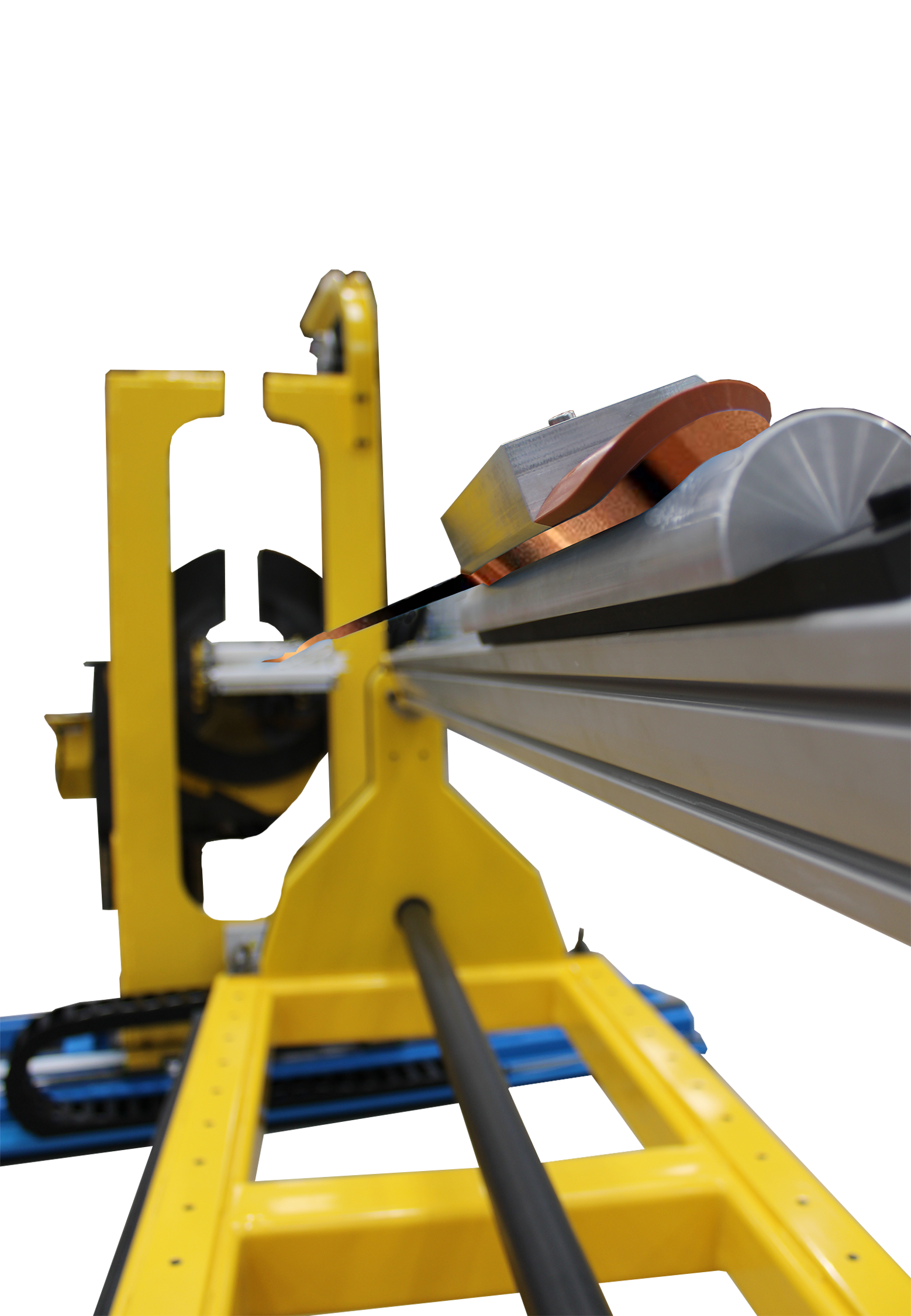
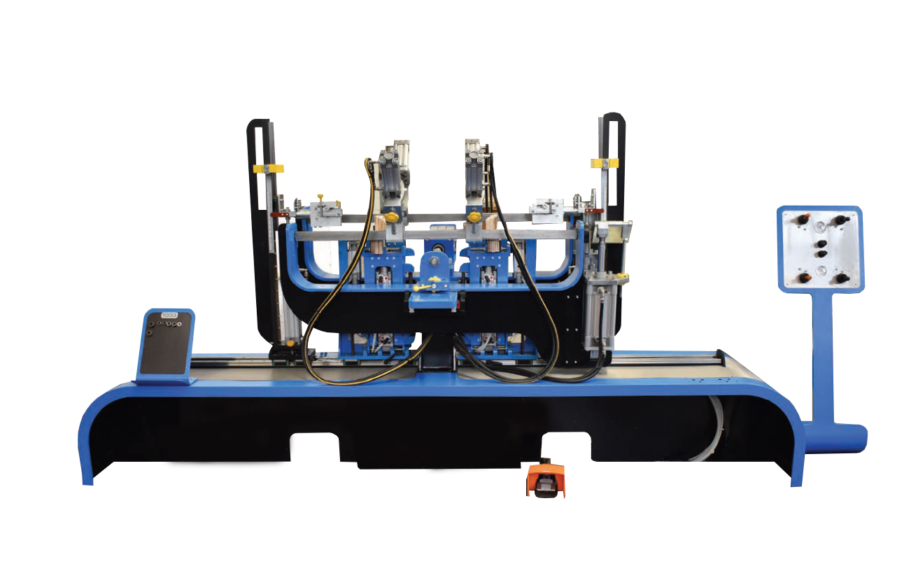
SSC – Straighten, strip and cut machine
for the rapid production of insulated straight bars for armature and rotor manufacture
The SSC line is designed to strip insulation from the ends of pre-insulated copper conductor (supplied on a drum) and deliver them as cut lengths.
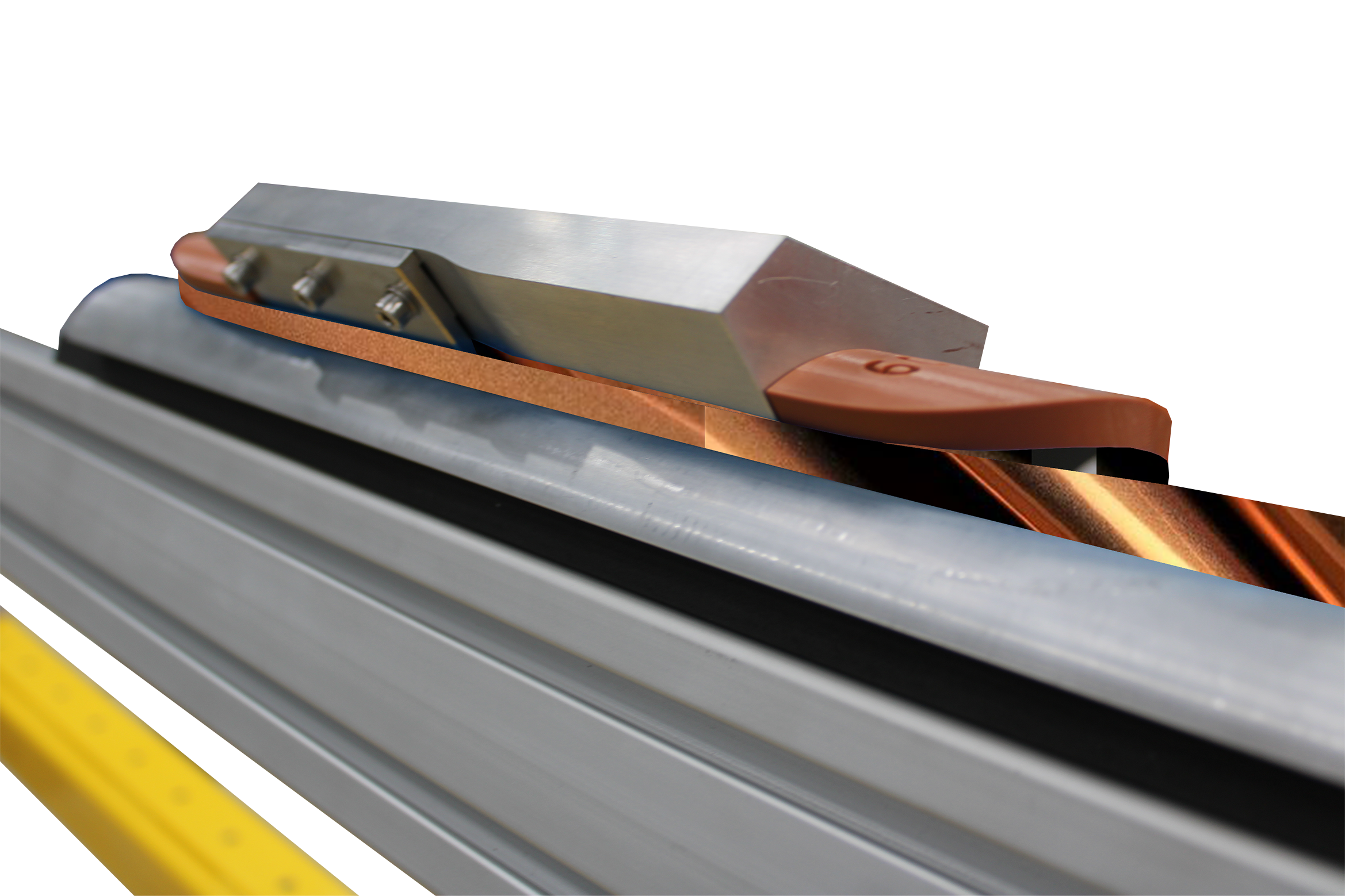
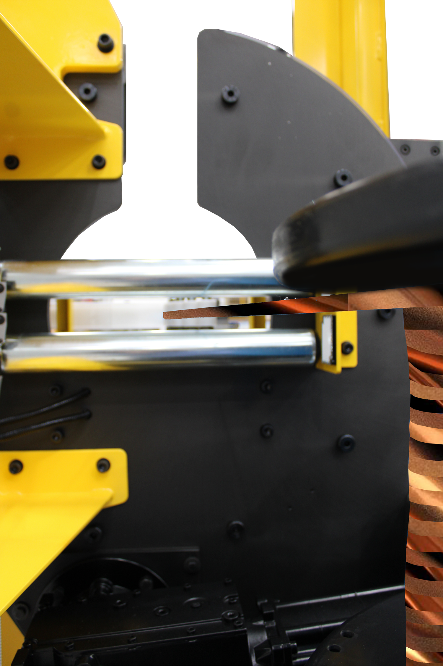
A drum of insulated conductor is fed from the pay-off drum stand and through the straightening unit. The conductor is then
pulled through the brush unit stripping the insulation with a counter rotating brush set.
The conductor is pulled through the machine by the caterpillar to a pre-set distance to the second brush unit and the next set of counter-rotating brushes. The
hydraulic guillotine cuts the conductor to length and drops the strip into the collection tray.
The tray indexes after each cut cycle, continuously delivering the final product to the pre-set total length and stripped end lengths.
The SSC line compromises the following modules:
![]() Pay-off Drum Stand
Pay-off Drum Stand
![]() Straightening Unit
Straightening Unit
![]() Brush Stripping & Clean Unit
Brush Stripping & Clean Unit
![]() Extractor
Extractor
![]() Caterpillar
Caterpillar
![]() Guillotine Cut Station
Guillotine Cut Station
![]() Delivery Chute/Collection Bench
Delivery Chute/Collection Bench
![]() HMI Control System
HMI Control System
Technical Specification
Copper Conduction Section
Min – 4mm x 1mm
Max – 18.. x 4mm
Insulation Stripped Length
30mm to 200mm
Conductor Cut Length
500mm to 800mm
Accuracy of Cut Length Conductors & Stripped Length of Ends
+/-2mm
Compressed Air Supply
Clean and dry at 5.5 bar min. pressure
BTU 100 – Band Tension Unit
Designed to apply preset tension to tapes and wires when banding armatures.
Technical Specification
Tension range
Up to 680 kg (1500 lbs)
Maximum tape width
30mm
Maximum wire diameter
3mm Ø
TS Traversing Saddle
Traverse length
1500mm as standard
Custom lengths available
The BTU100 accepts glass fibre tape up to 30mm wide and both round and flat steel wire.
Traversing saddle shown with band tension unit
![]() Tension Control
Tension Control
![]() Tension Adjustment
Tension Adjustment
![]() Straightening
Straightening
![]() Flexible Mounting
Flexible Mounting
![]() TS Traversing Saddle
TS Traversing Saddle